¶Pixel center positioning with 10level9
I seem to have a knack for asking questions that no one has an answer to. The most recent one has to do with Microsoft's Direct3D 10level9 technology, which lets you write Direct3D 11 applications that target DX9-class hardware. Specifically, I wanted to know the positioning of pixel centers. As usual, I couldn't find anything on this in the documented and online, so I had to do some investigation and testing.
Before I get to the results, some background. The way that conventionally 3D rendering works is by sampling on a regular grid -- if you imagine that you have a continuous image with all your polygons rendered out at infinite resolution and then drop a regular grid of pins onto it, the color beneath all of the pinpoints determines the color of the pixels of the final image. I say "conventionally" because once you throw in multisampling, centroid sampling, etc. it gets a bit more complex, although it's still sampling. The positions of these samples can also be thought as pixel centers. Now, as it turns out, the exact placement of these samples in the clip space coordinate system differs between rendering APIs:
- OpenGL, Direct3D 10/11: for x in [0, width), center is at (x+0.5)/(2*width)-1
- Direct3D 9: for x in [0, width), center is at x/(2*width)-1
Looking at this, you might think that the D3D9 placement is simpler and thus better, but in fact it's incredibly annoying. The reason is that the samples aren't centered, but are shifted up and left by half a pixel in the coordinate space. This means that, unlike the OpenGL placement, the coordinate space isn't symmetric about (0,0), and far worse, it makes your projection matrix dependent on viewport size. When setting up a regular 3D scene, the usual approach is to just ignore the problem and render with an uncompensated projection matrix. After all, who's going to notice if the image is shifted by half a pixel? Thankfully, Microsoft adjusted the coordinate system in Direct3D 10 to match OpenGL's half-integer samples, but everyone who still has to deal with D3D9 is stuck with this.
With 2D rendering, the story is different. In this case getting the mapping right is critical, and failure to do so can result in serious artifacts such as directional smearing with multiple passes. My favorite symptoms are one pixel gaps along two edges of the screen, missing corners on rectangles drawn using lines, and a 2x2 box filter blur across the entire image. Point sampling is often used as a hack to fix this problem, but that's dangerous because the half pixel offset means you're sampling exactly between texels -- and numerical accuracy issues can then introduce a lovely diagonal seam across your image. The right way is to adjust your projection matrix, and that means schlepping around the viewport-dependent offset all over the place as well as getting all the minus signs right (the Y offset is negated from the X offset!).
That brings us to 10level9, which is a special Direct3D 11 back end that interfaces to a Direct3D 9 device driver. Problem is, the pixel center offsets are different between D3D9 and D3D10/11, so the question I had was, do I need to correct for the offset? There were a few ways this could work out:
- 10level9 could ignore the difference, and the coordinate system would differ based on the underlying driver. This would be annoying but unsurprising; I still remember when you couldn't depend on glTexImage() getting red and blue straight for some formats and having the alpha blending cap set didn't necessarily mean the GPU did alpha blending.
- 10level9 could force software vertex processing, adjust the vertices on the CPU, and render the post-transformed geometry in hardware. This would be slower and not great for games or productivity apps, but OK for image processing where vertex transform load is low.
- 10level9 could rewrite the vertex shader to adjust the vertices. The problem with this is that there are hard limits on both instruction count and constant count for the base 9_1 profile that maps to vertex shader 2.0, and thus 10level9 might not be able to rewrite some vertex shaders to target shader model 2.0 hardware.
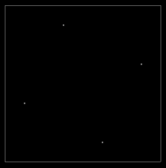
Now, I have a trick that I use to check pixel center alignment on graphics hardware, which is to render a series of micro-sized quads at varying offsets across a grid. A pixel will only light up when the sampling location at the pixel's center falls within one of these quads, and rendering a series of such quads with progressively nudged offsets across a grid thus produces a picture indicating the sampling locations. Here's what the output can look like:

This was a trick originally I used to catch graphics drivers that were evilly set to force full-scene antialiasing on against the application's will, which made games look great but totally screwed over the image processing operations I was trying to do. (When you're trying to do a tricky sampling pattern and packing four monochrome results into an ARGB output, the last thing you want is the driver shifting your samples and slathering a big blur pass over the result.) The image above is catching one such driver in the act, which is doing 4xAA on what is supposed to be a regular one sample per pixel frame buffer. You can see the positioning of the four sub-samples which contribute to the antialiased result. It's also good for detecting deviations in sampling rules, however, which is how it applies here:

As it turns out, no drama here, just a bullseye in the middle of the pixel -- which means that 10level9 does correct for the pixel offset between D3D9 and D3D10. I checked the WARP and reference drivers too, just in case this was a bug or misfeature in the hardware driver, but they gave the same result.
The next question I had was how. I'm embarrassed to say that I spent far too much time in WinDbg trying to coax this out of the 10level9 driver using symbols and tracing when all I actually needed to do was examine the output of the shader compiler. You see, in order to use 10level9, you have to compile your shaders in a special mode like vs_4_0_level_9_1:
Microsoft (R) Direct3D Shader Compiler 9.29.952.3111
Copyright (C) Microsoft Corporation 2002-2009. All rights reserved.
//
// Generated by Microsoft (R) HLSL Shader Compiler 9.29.952.3111
//
//
//   fxc /Tvs_4_0_level_9_1 /EVS shaders.fx
//
//
//
// Input signature:
//
// Name                 Index   Mask Register SysValue Format   Used
// -------------------- ----- ------ -------- -------- ------ ------
// POSITION                 0   xy          0     NONE  float   xy
// COLOR                    0   xyzw        1     NONE  float   xyzw
//
//
// Output signature:
//
// Name                 Index   Mask Register SysValue Format   Used
// -------------------- ----- ------ -------- -------- ------ ------
// COLOR                    0   xyzw        0     NONE  float   xyzw
// SV_Position              0   xyzw        1      POS  float   xyzw
//
//
// Runtime generated constant mappings:
//
// Target Reg                               Constant Description
// ---------- --------------------------------------------------
// c0                              Vertex Shader position offset
//
//
// Level9 shader bytecode:
//
    vs_2_0
    def c1, 0.00312500005, -0.00416666688, -1, 1
    def c2, 0.5, 1, 0, 0
    dcl_texcoord v0
    dcl_texcoord1 v1
    mov r0.xy, c1
    mad r0.xy, v0, r0, c0
    add oPos.xy, r0, c1.zwzw
    mov oT0, v1
    mov oPos.zw, c2.xyxy
// approximately 5 instruction slots used
vs_4_0
dcl_input v0.xy
dcl_input v1.xyzw
dcl_output o0.xyzw
dcl_output_siv o1.xyzw, position
mov o0.xyzw, v1.xyzw
mad o1.xy, v0.xyxx, l(0.003125, -0.004167, 0.000000, 0.000000), l(-1.000000, 1.000000, 0.000000, 0.000000)
mov o1.zw, l(0,0,0.500000,1.000000)
ret
// Approximately 4 instruction slots used
The shader compiler actually generates two versions of the vertex shader, one for Direct3D 9 class devices, and another for D3D10/11 capable ones. The telltale sign is the two lines in red, which compensate for the pixel offset. When compiling the shader for D3D9, the compiler reserves a special constant register for the offset and then emits additional logic to do the adjustment, like so:
oPos.xy += offset.xy * oPos.w;
Since the output position is in homogeneous coordinates, adding the offset scaled by w to the pre-divide position is equivalent to adding the offset to the post-divide position. This is apparently done at a higher level as the shader compiler is able to optimize this with the surrounding code: the multiply by w was omitted above because this was a 2D shader and the compiler noticed that w=1. In any case, the mystery of how the adjustment is done is solved -- not only is it done in the vertex shader, but the shader compiler modifies the shader so that 10level9 doesn't have to, and running into limits with the modified shader isn't a problem because the shader compiler can just enforce lower limits to allow for the adjustment. It also means you're taking the hit of an extra constant and an extra instruction for the adjustment, but for 2D stuff drawing big huge rectangles with four verts this is a non-issue.
tl;dr: 10level9 compensates for the different coordinate systems to make D3D9 hardware render with D3D10 rules and nice half-integer positioning, and all is good.